Character Model 3D
3D models are used to portray real-world and conceptual visuals for art, entertainment, simulation and drafting and are integral to many different industries, including virtual reality, video games, 3D printing. Here I will show a little bit of how to produce 3D character models through my own creativity and guidance from the lecturers.
01
Starting The Production

This project is started by creating a new file (File > New > Project Name) and importing images (View > Image Plan > Import Image > Image File > References Character Model) as a guide and reference for the production 3D model character.
02
Section Of the Head


Section Of the Head The head process is made using PolyCylinder mesh with resolution.the following:
• Axis Subdivisions: 8
• Subdivision Height: 1
• Subdivisions Caps: 1
The mode is changed to face mode, and then the surface on top of the cylinder highlighted to reduce the height of the polycylinder as desired. Then, change to a soft surface with the shortcut key (3). After that, shape the head according to the picture reference with the technique.
extrude (Edit Mesh > Extrude) upwards using additional tools, namely symmetry. (Click object > Shift > Ctrl > Right Click > Symmetry). Additionally, the vertex mode plays an important role, especially the lateral side, shaping the head to get the same look as the reference. (Right Click > Vertex).
03
Body Part


The body process is made using a PolyCylinder mesh with a resolution of the following:
• Axis Subdivisions: 8
• Subdivision Height: 1
• Subdivisions Caps: 1
Face mode is activated to reduce the height of the polycylinder for facilitate the body-shaping process according to the reference picture. Then, the rough surface (1) is converted into a soft surface with use the shortcut key (3) to get a clearer picture. Afterwards, body formation using the extrude technique (Edit Mesh >Extrude) upwards by using an additional tool, which is symmetry. (Click object > Shift > Ctrl > Right Click > Symmetry). Vertex is also used on both sides to get a perfect body shape, like in the reference picture. (Right Click > Vertex).
To combine two different objects, namely the body and the head. Select the mesh to be combined into one object. Select (Mesh > Combine) or click on Modelling Toolkit. The mesh will merge into one new polygon.
04
Left Eye Section
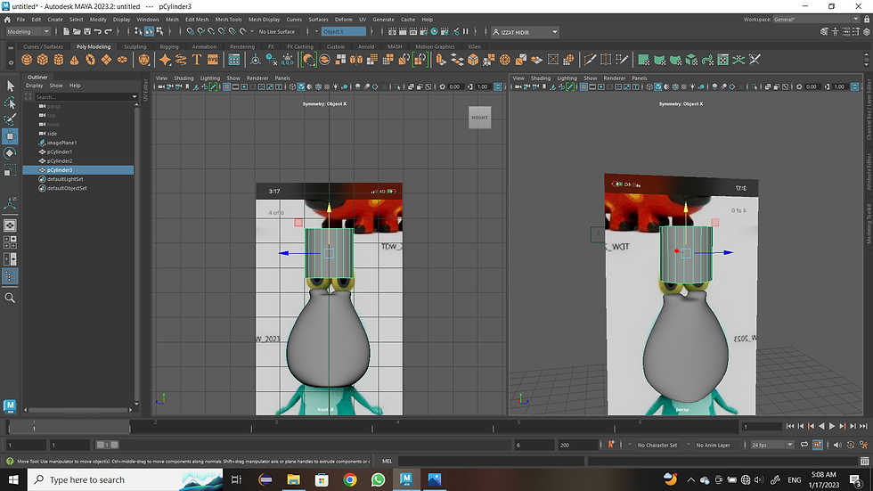

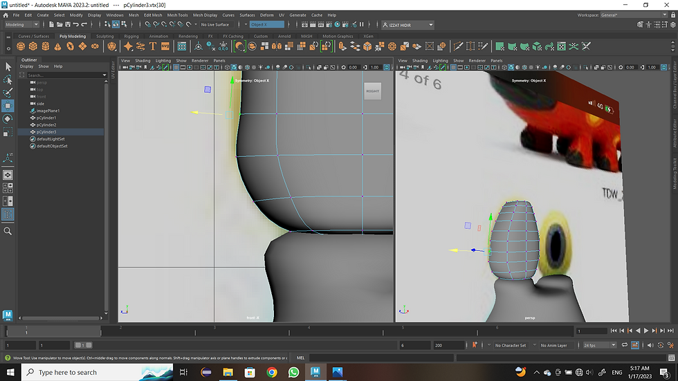

The body process is made using a PolyCylinder mesh with a resolution of the following:
• Axis Subdivisions: 8
• Subdivision Height: 1
• Subdivisions Caps: 1
Once done, change the setting to mesh PolyCylinder. Highlight on part of the top surface of the mesh polycylinder. After that, switch to face mode (Right Click > Face). Then, use the move tools (W). To reduce the height of the mesh polycylinder accordingly suitability. After that, the highlight is back on the surface meshPolyCyclinder. For the next formation, use extrude technique (Ctrl > E) to form eyes. Repeat the extrude technique until it gets the right fit. After that, change it.to a soft surface (Smooth Face) (3) for the next determination. The use of vertices is also very important for tidying up mesh polycylinder, especially on the sides. Use of techniques vertex (Right Click > Vertex) on the side of the cylinder for develop a cylindrical shape according to the reference picture. Additional On the other hand, the upper part of the mesh polycylinder uses the technique (Mesh > Fill Hole). The poly will be perforated at the top. Then, change to edge (Right Click > Edge) and highlight the part edge of the object around the object on the perforated surface. Next, Fill the hole with (Edit Mesh > Poke) to get 1 vertex on the top surface of the mesh polycylinder.
05
Right Eye Section


The body process is made using a PolyCylinder mesh with a resolution of the following:
• Axis Subdivisions: 8
• Subdivision Height: 1
• Subdivisions Caps: 1
Using the following settings, highlight the surface polycylinder. Then, activate the face mode (Right Click > Face). After than that, use the move tools (W) technique to reduce height of the object as appropriate. After that, highlight on the PolyCylinder surface for the next step. Extrude technique (Ctrl > E) on that surface to get excess vertices onside part to facilitate the finishing process at the step the last In the process image, the extrude technique is used four times. At the end, use the vertex (Right Click > Vertex) in the middle section to further develop the shape on the upper part with using move tools (W). After that, switch to the surface soft (Smooth Face) (3) for the next step use of vertices plays the role of tidying up the sides on the mesh polycylinder, according to the reference source. Other than that, the top mesh polycylinder was created using the (Mesh > Fill Hole) technique. The poly will be perforated at the top. Then, switch to edge (right-click > Edge) and highlight the edge of the surrounding objects on perforated surfaces. Next, fill the hole with (Edit Mesh > Poke) to get 1 vertex on the surface of the MeshPolyCylinder.
Results From The Production Process Of Head, Body, And Eyes

06
Left Hand Side


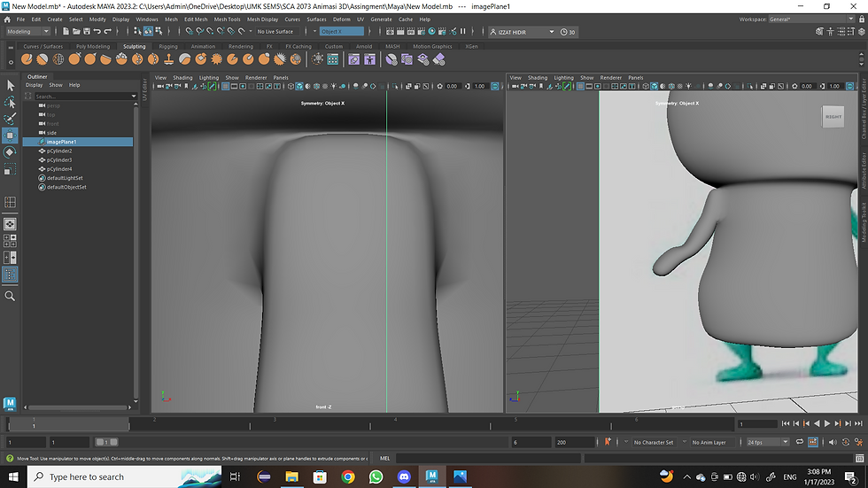

Once you have selected the four series of surfaces on the left side, using extrude technique by pulling out from the original surface. Using shortcut key that has been provided (Ctrl > E) and start the surface which has been selected to be pulled out. Next, draw the surface down. Use the shortcut key (Ctrl > W) to get it extrude the continuation of the hand at different positions so that looks the same as the reference already provided. Change to soft surface with the shortcut key (3).
07
Right Hand Side

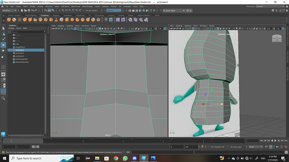


For the production of the right hand, four surfaces are selected on the right side. To shape the hand, the extrude technique is used. The method is (Ctrl > E). Where the surface is pulled out adequately. Then repeat the same steps. Drop down a little by using the shortcut key (Ctrl > W) so that it is easier to extrude on the connection part until it looks perfect, like in the diagram. Finished on that part, switch to surface soft (3) so that it is easy to edit back on the relevant part by using vertices (Right Click > Vertex).
08
Left Leg Process

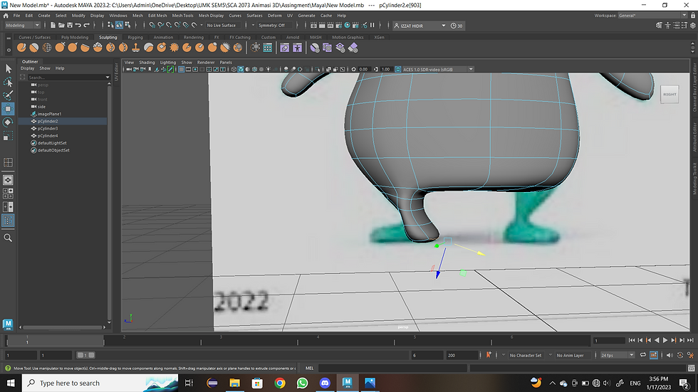
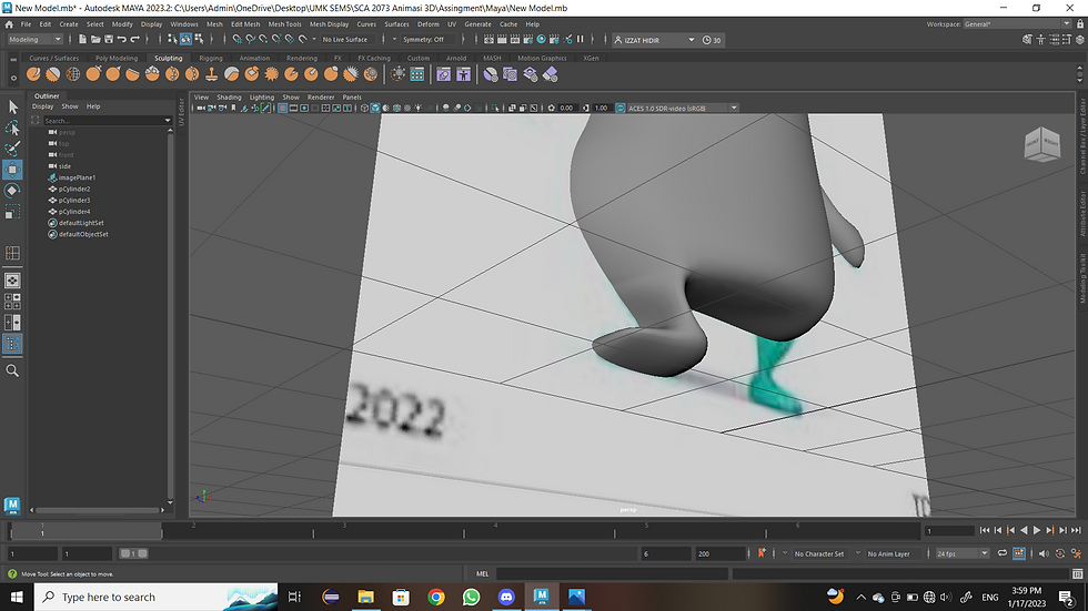

For the production of the left leg. Begin by making the surface soft (Smooth Face) (3). After that, go to the bottom surface of the character. Highlight on the appropriate surface to create legs. The first is to activate the face mode (Right Click > Face). After that, use the extrude technique (Ctrl > E) and then use the move tool (W) to pull down at your own convenience. After that, highlight the lower surface on the left side. Extrude (Ctrl > E) and move the move tool (W) to pull to the side until it reaches the end. To tidy up foot shape (Right Click > Vertex) to activate Vertex mode. Between the vertex, it is important to be prepared in the soles of the feet, the end legs, and the upper legs. This is because there are some vertices inside. So, the use of vertices can help to tidy vertices, such as other vertices. However, face mode is also activated (Right Click > Face) to expand a little on the legs according to suitability.
09
Right Leg Process
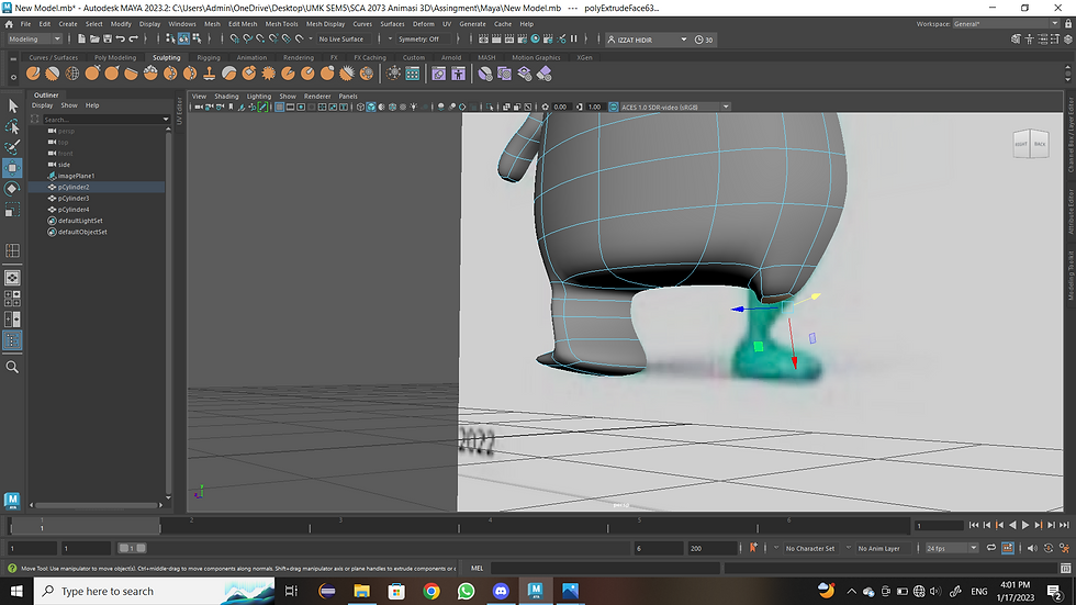


On the right leg. The process is almost the same as the production of legs. The first change to a soft surface (Smooth Face) (3) is to facilitate the use of extrude (Ctrl > E) and move techniques tools (W). After that, highlight the selected surface according to your own creativity. Activate face mode (Right Click > Face), then change to move tools (W). Extrude (Ctrl > E) the selected part by dragging it down to extend the leg. After that, the highlight goes back to the surface in the lower left to develop the surface. Activate vertex mode (Right > Click) and use the move tools (W) to expand the surface in the direction of appropriate. For the production of legs in the last process. Highlights on the right side of the foot Then activate extrude mode (Ctrl > E) and use the move tools (W) to draw the surface as appropriate, as in the reference picture. The legs on the right side are already formed. But the next tidy step is to use vertex (Right Click > Vertex) to tidy up certain parts, like the top, bottom, and sides. This is because during the extrusion process, the surface becomes uneven. Not only using vertices but also using other modes such as edge (Ctrl > Edge) and face (Ctrl > Face) for the housekeeping process.
Results From Hand And Eyes Production Process


